In part 2 we implemented metrics and basic register reads (one at a time). Now we will implement chunked (block) reads since this is more efficient as it involves fewer TCP round trips. At the end, we’ll also try writing to the inverter’s control registers to force the battery to charge and stop.
Recall that we modelled the sensors of the inverter using a structure:
structure Sensor where
  name                : String
  unique_id           : String
  address             : UInt16
  input_type          : InputType
  data_type           : DataType
  count               : Option Nat        := none
  swap                : Option Swap       := none
  scale               : Option JsonNumber := none
  precision           : Option Nat        := none
  -- (more fields)
For example, inverter temperature is encoded as:
-- `int16` with a scale of `0.1`, so a raw `253` reads as 25.3 °C.
def inverterTemperature : Sensor :=
  { name                := "Inverter temperature"
    unique_id           := "sg_inverter_temperature"
    address             := 5007
    input_type          := .input
    data_type           := .int16
    scale               := some ⟨1, 1⟩ -- 1 × 10^(-1) = 0.1
    precision           := some 1
  }
We want to read one of these sensors and store its result. Let’s put the
reading alongside the sensor in a Slot:
structure Reading where
  raw       : Array UInt16
  read_at   : Timestamp     -- for humans, UTC
  read_mono : Nat           -- for liveness checks, IO.monoNanosNow

structure Slot where
  sensor    : Sensor
  reading   : Option Reading := none
This is fine, but how large should raw be? What if it’s empty? Does empty
mean that the read failed? What if the field is two 16-bit words and raw has just
one? What if it’s larger than the actual size of the sensor?
We can do better with dependent types:
structure Reading (n : Nat) where
  raw       : Vector UInt16 n
  read_at   : Timestamp   -- for humans, UTC
  read_mono : Nat         -- for liveness checks, IO.monoNanosNow
Now a reading is parameterised by n : Nat, and raw is a vector of UInt16 of length exactly n.
If you try to make a vector of 3 elements and claim it is a Vector Nat 4, it will not compile:
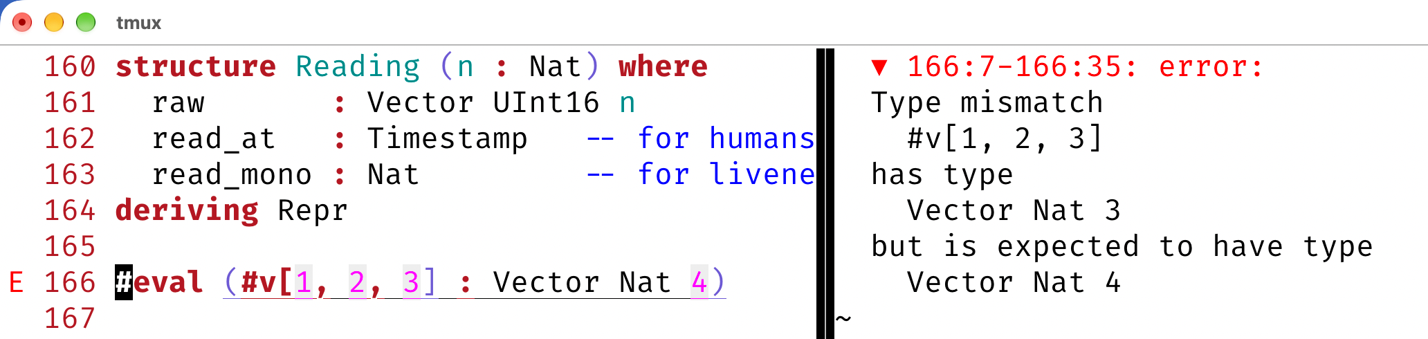
(I’m using the lean.nvim Neovim plugin. VS Code shows the same information.)
Now the reading in a Slot can refer to the actual register size via the function Sensor.words:
def Sensor.words (s : Sensor) : Nat :=
  match s.data_type with
  | .int16  | .uint16 => 1
  | .int32  | .uint32 => 2
  | .string           => s.count.getD 1

structure Slot where
  sensor    : Sensor
  reading   : Option (Reading sensor.words) := none
Inverter temperature is one register, while DC power is two:
-- `uint32` spanning registers 5016 and 5017, low word first.
def totalDcPower : Sensor :=
  { name                := "Total DC power"
    unique_id           := "sg_total_dc_power"
    address             := 5016
    input_type          := .input
    data_type           := .uint32
    swap                := some .word
    scale               := some ⟨1, 0⟩
    precision           := some 0
    -- (more fields)
  }
We can check this with #eval:
#eval inverterTemperature.words   -- 1
#eval totalDcPower.words          -- 2
Since Sensor.words is an ordinary function, Lean can evaluate it while
type checking. So Reading inverterTemperature.words is Reading 1, and
rfl proves it:
example : Reading inverterTemperature.words = Reading 1 := rfl
example : Reading totalDcPower.words        = Reading 2 := rfl
A slot that hasn’t been read yet just leaves reading at its default of none.
Notice that the type of the reading mentions the slot’s own sensor:
def emptySlot : Slot := { sensor := inverterTemperature }

#check emptySlot.reading -- emptySlot.reading : Option (Reading emptySlot.sensor.words)
Now let’s fill in some readings, giving each one exactly as many words as its sensor needs:
def t0 : Timestamp := Timestamp.ofSecondsSinceUnixEpoch 1793050000 -- 2026-10-26T21:26:40

def tempSlot : Slot :=
  { sensor  := inverterTemperature
    reading := some { raw := #v[253], read_at := t0, read_mono := 0 } }

def dcSlot : Slot :=
  { sensor  := totalDcPower
    reading := some { raw := #v[1480, 0], read_at := t0, read_mono := 0 } }

#eval tempSlot.reading.map (·.raw.toArray)   -- some #[253]
#eval dcSlot.reading.map (·.raw.toArray)     -- some #[1480, 0]
If we hand the DC power sensor only one word, the definition doesn’t compile:
def badSlot : Slot :=
  { sensor  := totalDcPower
    reading := some { raw := #v[1480], read_at := t0, read_mono := 0 } }
error: Type mismatch
#v[1480]
has type
Vector Nat 1
but is expected to have type
Vector UInt16 totalDcPower.words
The check holds up under updates too. If we take the temperature slot and swap in a different sensor, the old one-word reading no longer matches:
def swapped : Slot := { tempSlot with sensor := totalDcPower }error: Type mismatch
__src✝.reading
has type
Option (Reading __src✝.sensor.words)
but is expected to have type
Option (Reading totalDcPower.words)
The payoff comes when we read the data back. Lean knows how long raw is,
so it can check each index while type checking. We don’t need ! or ?,
and there’s nothing that can panic at runtime:
def tempRaw (r : Reading inverterTemperature.words) : UInt16 := r.raw[0]  -- ok
def dcHigh  (r : Reading totalDcPower.words)        : UInt16 := r.raw[1]  -- ok

def tempBad (r : Reading inverterTemperature.words) : UInt16 := r.raw[1]
error: failed to prove index is valid, possible solutions:
...
r : Reading inverterTemperature.words
⊢ 1 < inverterTemperature.words
The temperature sensor has exactly one register, so index 1 doesn’t exist,
and Lean rejects tempBad before it ever runs.
Read blocks Link to heading
Now let’s define a read block. This has a starting address, from which we will read nr_words words, and an
array of slots. The idea is that the range [address, address + nr_words) will cover any register in slots.
structure ReadBlock where
  input_type  : InputType -- .input | .holding
  address     : Nat
  nr_words    : Nat
  slots       : Array Slot
With this definition, there’s nothing stopping us from creating a nonsensical read block. There are four ways it can go wrong:
nr_wordsis more than Modbus allows in one read.- A slot’s sensor is in the other register space (input vs holding).
- Two slots claim the same register (i.e. overlap).
- A slot sits partly or completely outside
[address, address + nr_words).
Rather than checking these at runtime, we make each one a field of the
structure. A field whose type is a Prop holds a proof, so a ReadBlock
value can’t exist unless all four conditions hold:
def Sensor.start (s : Sensor) : Nat := s.address.toNat
def Sensor.stop  (s : Sensor) : Nat := s.start + s.words  -- [start, stop) is half-open

def Slot.sensors (slots : Array Slot) : List Sensor :=
  slots.toList.map (·.sensor)

structure ReadBlock where
  input_type  : InputType
  address     : Nat
  nr_words    : Nat
  slots       : Array Slot

  fits        : Modbus.ValidReadQuantity nr_words
  same_type   : ∀ s ∈ Slot.sensors slots, s.input_type = input_type
  disjoint    : (Slot.sensors slots).Pairwise (·.stop ≤ ·.start)
  inside      : ∀ s ∈ Slot.sensors slots,
                  address ≤ s.start ∧ s.stop ≤ address + nr_words
To try this out, here are two more sensors:
-- Signed: negative while the battery is charging.
def batteryPower : Sensor :=
  { name       := "Battery power"
    unique_id  := "sg_battery_power"
    address    := 5213
    input_type := .input
    data_type  := .int32
    swap       := some .word
    -- (more fields)
  }

-- Scale `0.01`: a raw `5002` is 50.02 Hz.
def gridFrequency : Sensor :=
  { name       := "Grid frequency"
    unique_id  := "sg_grid_frequency"
    address    := 5241
    input_type := .input
    data_type  := .uint16
    scale      := some ⟨1, 2⟩
    -- (more fields)
  }
The battery power takes registers 5213 and 5214, and the grid frequency is at
5241. So a 29-word read starting at 5213 covers both. Because the sensors are
literals, decide can close all four proofs: Lean just evaluates each
proposition.
def batteryBlock : ReadBlock :=
  { input_type := .input
    address    := 5213
    nr_words   := 29
    slots      := #[⟨batteryPower, none⟩, ⟨gridFrequency, none⟩]
    fits       := by decide
    same_type  := by decide
    disjoint   := by decide
    inside     := by decide }
Now let’s break each condition in turn.
Too many words Link to heading
A single Modbus read can return at most 125 registers:
abbrev maxReadQuantity : Nat := 125
abbrev ValidReadQuantity (n : Nat) : Prop := 1 ≤ n ∧ n ≤ maxReadQuantity
Ask for 126 words and fits fails:
error: Tactic `decide` proved that the proposition
  Modbus.ValidReadQuantity 126
is false
The Modbus client’s readInputRegisters requires the same ValidReadQuantity
proof. So once a block has been built, reading it needs no extra checks.
Wrong register space Link to heading
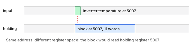
Input and holding registers are two separate address spaces. Input register
5007 and holding register 5007 have nothing to do with each other. A block
marked .holding can’t hold the inverter temperature, which is an input
register:
error: Tactic `decide` proved that the proposition
  ∀ (s : Sensor), s ∈ Slot.sensors #[{ sensor := inverterTemperature }] → s.input_type = InputType.holding
is false
Overlapping slots Link to heading
Battery power is an int32, so it takes registers 5213 and 5214. Suppose we
mistype the grid frequency’s address as 5214:
def typo : Sensor := { gridFrequency with address := 5214 }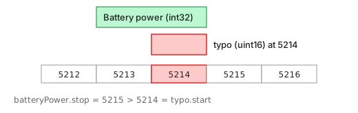
disjoint says that each sensor has to stop at or before the start of the
next one. Here that fails:
error: Tactic `decide` proved that the proposition
  List.Pairwise (fun x1 x2 => x1.stop ≤ x2.start)
    (Slot.sensors #[{ sensor := batteryPower }, { sensor := typo }])
is false
Since Pairwise compares every slot with every slot after it, the same
condition also means the slots must be in ascending address order.
Slot outside the block Link to heading
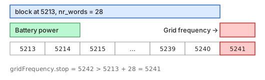
This is the valid block from above, but with an off-by-one: 28 words instead
of 29. The block now covers [5213, 5241), so the grid frequency at 5241
falls just past the end:
error: Tactic `decide` proved that the proposition
  ∀ (s : Sensor),
    s ∈ Slot.sensors #[{ sensor := batteryPower }, { sensor := gridFrequency }] → 5213 ≤ s.start ∧ s.stop ≤ 5213 + 28
is false
Without this check, the read would succeed and we would get a 28-word vector
back. Then we would try to slice register 5241 out of it, which is past the
end. The inside proof is what makes that slice safe.
Slicing a block read Link to heading
One Modbus request returns the whole block as a Vector UInt16 b.nr_words.
Now we need to cut it up, giving each slot exactly its sensor’s words:
def ReadBlock.slice (b : ReadBlock) (v : Vector UInt16 b.nr_words) (i : Fin b.slots.size) :
    Vector UInt16 b.slots[i].sensor.words :=

  let s      := b.slots[i].sensor
  let offset := s.start - b.address

  have hin : b.address ≤ s.start ∧ s.stop ≤ b.address + b.nr_words := b.inside s (b.mem_sensors i)

  Vector.ofFn fun (k : Fin s.words) =>
    v[offset + k]'(by
      have hk : k.val < s.words := k.isLt
      have hstop : s.stop = s.start + s.words := rfl
      omega
      )
The types tell us about the constraints:
v : Vector UInt16 b.nr_wordsis the raw block read, so it has to be exactly as long as the block.i : Fin b.slots.sizeis an index that is guaranteed to be a valid slot, sob.slots[i]needs no bounds check.- The return type
Vector UInt16 b.slots[i].sensor.wordsmatches what aSlot’sReadingneeds. That’sReading sensor.wordsfrom earlier.
The body works out where the sensor starts within the block, namely offset. Then
it builds the result with Vector.ofFn, which takes a function from
Fin s.words to elements. A vector built that way has length s.words by
construction, so getting the length right needs no proof. The only proof
needed is that each lookup v[offset + k] stays in bounds. At that point,
the goal is:
s      : Sensor := b.slots[i].sensor
offset : Nat    := s.start - b.address
hin    : b.address ≤ s.start ∧ s.stop ≤ b.address + b.nr_words
k      : Fin s.words
hk     : ↑k < s.words
hstop  : s.stop = s.start + s.words
⊢ offset + ↑k < b.nr_words
This is linear arithmetic, and omega can do the proof. If we were proving it by
hand with pen and paper we would do the following:
offset + k  =  (s.start - b.address) + k         -- definition of offset
            <  (s.start - b.address) + s.words   -- hk
            =  s.start + s.words - b.address     -- rearranging, needs b.address ≤ s.start (hin)
            =  s.stop  - b.address               -- hstop
            ≤  b.nr_words                        -- s.stop ≤ b.address + b.nr_words (hin)
The interesting hypothesis is hin. It comes straight from the block’s
inside field, together with a small lemma, mem_sensors, which says that
b.slots[i].sensor is in Slot.sensors b.slots. Both halves of hin get
used. The left half matters because Nat subtraction truncates at zero. If
the sensor started before the block, then s.start - b.address would be 0,
and the rearranging step would fail. For example, with s.start = 5,
b.address = 7 and s.words = 3, the left side is 0 + 3 = 3 but the right
side is 8 - 7 = 1.
Delete the have hin line and omega gives up:
error: omega could not prove the goal:
a possible counterexample may satisfy the constraints
  ...
Without inside, nothing ties the sensor’s position to the size of the
block, and an out-of-bounds read is a real possibility. So the proof we gave
when building the block pays off when we use it!
We can watch it work on batteryBlock without talking to the inverter. Instead
of real sensor values, we fill a fake read with labels: the word that came
from register 5213 is set to the number 5213, the word from 5214 is set to
5214, and so on. Then any word that slice returns tells us which register
it came from:
def fakeRead : Vector UInt16 batteryBlock.nr_words :=
  Vector.ofFn fun k => (5213 + k.val).toUInt16

#eval fakeRead.toArray
-- #[5213, 5214, 5215, ..., 5240, 5241]

#eval (batteryBlock.slice fakeRead ⟨0, by decide⟩).toArray   -- battery power
-- #[5213, 5214]

#eval (batteryBlock.slice fakeRead ⟨1, by decide⟩).toArray   -- grid frequency
-- #[5241]
The battery power gets its two registers, and the grid frequency gets the single register at offset 28, the last word of the block.
Reading a block Link to heading
With slice in place, reading a block is short:
/-- Read the block's registers in one request and record a reading in every slot. -/
def ReadBlock.read (b : ReadBlock) (c : Modbus.Client) : Modbus.M ReadBlock := do
  let addr := b.address.toUInt16
  let v ← match b.input_type with
    | .input   => c.readInputRegisters   addr b.nr_words b.fits
    | .holding => c.readHoldingRegisters addr b.nr_words b.fits
  let readAt ← Timestamp.now
  let readMono ← IO.monoNanosNow

  return b.setReadings fun i => some ⟨b.slice v i, readAt, readMono⟩
The block’s fits field is passed straight to the Modbus client as the proof
that nr_words is a legal read size. The client returns a
Vector UInt16 b.nr_words, which is exactly what slice expects. Then
setReadings fills in every slot. It returns a new ReadBlock, so it has to
supply the four proofs again. fits carries over unchanged, and the other
three only talk about the slots’ sensors. A small lemma shows that replacing
the readings leaves Slot.sensors unchanged, so the old proofs still apply.
Real sensors are loaded from JSON at runtime, so they aren’t literals and
decide can’t help. Instead, ReadBlock.make? checks the four conditions
at runtime and returns an Option ReadBlock:
def ReadBlock.make? (ty : InputType) (addr n : Nat) (slots : Array Slot) : Option ReadBlock :=
  if h : (Modbus.ValidReadQuantity n)
       ∧ (∀ s ∈ Slot.sensors slots, s.input_type = ty)
       ∧ (Slot.sensors slots).Pairwise (·.stop ≤ ·.start)
       ∧ (∀ s ∈ Slot.sensors slots, addr ≤ s.start ∧ s.stop ≤ addr + n)
    then
      have ⟨fits, same_type, disjoint, inside⟩ := h
      some ⟨ty, addr, n, slots, fits, same_type, disjoint, inside⟩
    else
      none
The if h : ... form makes the check’s result available as a proof h in
the then branch, and those four proofs go straight into the structure.
Main.lean groups the sensors greedily: it keeps adding the next sensor to
the current block for as long as make? succeeds, and starts a new block
when it fails.
For the 29 sensors I’m monitoring, that gives three blocks. With
SUNGROWD_DEBUG=1 we can see the Modbus traffic (metrics trimmed, and the
last response shortened):
❯ SUNGROWD_DEBUG=1 .lake/build/bin/sungrowd
TX 00 00 00 00 00 06 01 | 04 13 8f 00 0b   mbap tx=0 len=6 unit=1
RX 00 00 00 00 00 19 01 | 04 16 01 ae 00 00 00 00 0f 19 00 19 06 7a 00 00 00 00 00 00 03 bd 00 00   mbap tx=0 len=25 unit=1
solar_inverter_temperature_celsius      43.0 °C
solar_pv_string1_voltage_volts          386.5 V
solar_pv_string1_current_amperes        2.5 A
solar_pv_string2_voltage_volts          165.8 V
solar_pv_string2_current_amperes        0.0 A
solar_pv_power_watts                    957 W
TX 00 01 00 00 00 06 01 | 04 14 5d 00 1d   mbap tx=1 len=6 unit=1
RX 00 01 00 00 00 3d 01 | 04 3a 00 e0 00 00 00 00 00 00 00 00 00 00 00 00 00 00 00 00 00 00 00 00 00 00 00 00 00 00 00 00 00 00 00 00 00 00 00 00 00 00 00 00 00 00 00 00 00 00 00 00 00 00 00 00 00 00 13 8b   mbap tx=1 len=61 unit=1
solar_battery_power_watts               224 W
solar_grid_frequency_hertz              50.03 Hz
TX 00 02 00 00 00 06 01 | 04 32 c7 00 30   mbap tx=2 len=6 unit=1
RX 00 02 00 00 00 63 01 | 04 60 00 00 00 0d 00 14 3a 77 ... 0b b7 00 00   mbap tx=2 len=99 unit=1
solar_running_state                     0 (Running)
solar_power_flow_status                 13 (PV generating, Battery discharging, Positive Load Power)
...
That’s three round trips instead of 29. Each request is function code 04
(read input registers), followed by a start address and a count:
| Request | Start | Count | Covers |
|---|---|---|---|
13 8f 00 0b | 5007 | 11 | inverter temperature … total DC power |
14 5d 00 1d | 5213 | 29 | battery power, grid frequency (our batteryBlock) |
32 c7 00 30 | 12999 | 48 | running state … total exported energy |
We can decode the first response by hand to check slice. After the byte
count 16 (22 bytes = 11 words), the words are:
offset  0  01ae  register 5007  inverter temperature  430 × 0.1 = 43.0 °C
offset  3  0f19  register 5010  MPPT1 voltage        3865 × 0.1 = 386.5 V
offset  4  0019  register 5011  MPPT1 current          25 × 0.1 = 2.5 A
offset  5  067a  register 5012  MPPT2 voltage        1658 × 0.1 = 165.8 V
offset  9  03bd  register 5016  total DC power, low word  = 957
offset 10  0000  register 5017  total DC power, high word = 0      → 957 W
The second block is mostly zeros because nothing we monitor lives between
battery power and grid frequency. We read those 26 registers anyway, since
one larger request is cheaper than two small ones. The block starts with
00e0 0000 (battery power, low word first: 224 W) and ends with 138b
(5003 × 0.01 = 50.03 Hz).
Write test Link to heading
So far we have only read from the inverter. It also has writable holding
registers that control its energy management system (EMS). Three consecutive
registers starting at 13049 (32 f9 in the traffic below) matter here:
| Register | Meaning | Values |
|---|---|---|
| 13049 | EMS mode | 0 self-consumption, 2 forced |
| 13050 | Forced command | 0xAA (170) charge, 0xBB (187) discharge, 0xCC (204) stop |
| 13051 | Forced power | watts, used for charge and discharge |
In self-consumption mode, which is the normal setting, the inverter decides for itself. Surplus PV charges the battery, and the battery covers the house load when PV falls short. In forced mode, it follows the command register instead.
Each sungrowd write does three Modbus requests: read the three registers
(function code 03), write all three at once (function code 10), and read
them back. It then prints a JSON record of what it intended, what was there
before, and what is there after. A successful write has “after” equal to
“intended”.
The full output lists 29 metrics. Below, I’ve kept only the ones that show where the power is going. Note the signs: battery power is negative while the battery charges and positive while it discharges, and grid power is positive while exporting and negative while importing.
First, check status:
❯ .lake/build/bin/sungrowd
solar_pv_power_watts                    1586 W
solar_battery_power_watts               -1208 W
solar_running_state                     0 (Running)
solar_power_flow_status                 3 (PV generating, Battery charging)
solar_load_power_watts                  260 W
solar_grid_power_watts                  0 W
solar_inverter_ac_power_watts           260 W
Check the control status:
❯ SUNGROWD_DEBUG=1 .lake/build/bin/sungrowd control
TX 00 00 00 00 00 06 01 | 03 32 f9 00 03   mbap tx=0 len=6 unit=1
RX 00 00 00 00 00 09 01 | 03 06 00 00 00 cc 00 00   mbap tx=0 len=9 unit=1
self_consumption stop 0 W  raw #[0, 204, 0]
Force it to stop:
❯ SUNGROWD_DEBUG=1 .lake/build/bin/sungrowd write forced stop
TX 00 00 00 00 00 06 01 | 03 32 f9 00 03   mbap tx=0 len=6 unit=1
RX 00 00 00 00 00 09 01 | 03 06 00 00 00 cc 00 00   mbap tx=0 len=9 unit=1
TX 00 01 00 00 00 0d 01 | 10 32 f9 00 03 06 00 02 00 cc 00 00   mbap tx=1 len=13 unit=1
RX 00 01 00 00 00 06 01 | 10 32 f9 00 03   mbap tx=1 len=6 unit=1
TX 00 02 00 00 00 06 01 | 03 32 f9 00 03   mbap tx=2 len=6 unit=1
RX 00 02 00 00 00 09 01 | 03 06 00 02 00 cc 00 00   mbap tx=2 len=9 unit=1
{"recorded_at": "2026-10-24T23:03:03Z",
 "intended":
 {"forced_power_w": 0,
  "ems_mode_label": "forced",
  "ems_mode": 2,
  "ems_command_label": "stop",
  "ems_command": 204},
 "before":
 {"forced_power_w": 0,
  "ems_mode_label": "self_consumption",
  "ems_mode": 0,
  "ems_command_label": "stop",
  "ems_command": 204},
 "after":
 {"forced_power_w": 0,
  "ems_mode_label": "forced",
  "ems_mode": 2,
  "ems_command_label": "stop",
  "ems_command": 204}}
Check what’s happening:
❯ .lake/build/bin/sungrowd control
forced stop 0 W  raw #[2, 204, 0]


❯ .lake/build/bin/sungrowd
solar_pv_power_watts                    962 W
solar_battery_power_watts               0 W
solar_running_state                     2048 (Running in compulsory (forced) mode)
solar_power_flow_status                 17 (PV generating, Exporting Power)
solar_load_power_watts                  208 W
solar_grid_power_watts                  659 W
solar_inverter_ac_power_watts           881 W
Now force charge at 1230 W:
❯ SUNGROWD_DEBUG=1 .lake/build/bin/sungrowd write forced charge 1230
TX 00 00 00 00 00 06 01 | 03 32 f9 00 03   mbap tx=0 len=6 unit=1
RX 00 00 00 00 00 09 01 | 03 06 00 02 00 cc 00 00   mbap tx=0 len=9 unit=1
TX 00 01 00 00 00 0d 01 | 10 32 f9 00 03 06 00 02 00 aa 04 ce   mbap tx=1 len=13 unit=1
RX 00 01 00 00 00 06 01 | 10 32 f9 00 03   mbap tx=1 len=6 unit=1
TX 00 02 00 00 00 06 01 | 03 32 f9 00 03   mbap tx=2 len=6 unit=1
RX 00 02 00 00 00 09 01 | 03 06 00 02 00 aa 04 ce   mbap tx=2 len=9 unit=1
{"recorded_at": "2026-10-24T23:04:07Z",
 "intended":
 {"forced_power_w": 1230,
  "ems_mode_label": "forced",
  "ems_mode": 2,
  "ems_command_label": "charge",
  "ems_command": 170},
 "before":
 {"forced_power_w": 0,
  "ems_mode_label": "forced",
  "ems_mode": 2,
  "ems_command_label": "stop",
  "ems_command": 204},
 "after":
 {"forced_power_w": 1230,
  "ems_mode_label": "forced",
  "ems_mode": 2,
  "ems_command_label": "charge",
  "ems_command": 170}}


❯ .lake/build/bin/sungrowd
solar_pv_power_watts                    962 W
solar_battery_power_watts               -1229 W
solar_running_state                     2048 (Running in compulsory (forced) mode)
solar_power_flow_status                 43 (PV generating, Battery charging, Positive Load Power, Importing Power)
solar_load_power_watts                  1726 W
solar_grid_power_watts                  -2140 W
solar_inverter_ac_power_watts           -420 W
The battery is charging at 1229 W, right on the 1230 W target, even though the load is now higher than the PV output. Our washing machine was running, which explains the 1726 W load, so most of the 2140 W grid import is for the washing machine, not the battery. The part going to the battery shows up in the inverter’s AC power: −420 W means the inverter is drawing about 420 W from the grid to top up the 962 W of PV.
And finally, revert to self-consumption mode:
❯ SUNGROWD_DEBUG=1 .lake/build/bin/sungrowd write self-consumption
TX 00 00 00 00 00 06 01 | 03 32 f9 00 03   mbap tx=0 len=6 unit=1
RX 00 00 00 00 00 09 01 | 03 06 00 02 00 aa 04 ce   mbap tx=0 len=9 unit=1
TX 00 01 00 00 00 0d 01 | 10 32 f9 00 03 06 00 00 00 cc 00 00   mbap tx=1 len=13 unit=1
RX 00 01 00 00 00 06 01 | 10 32 f9 00 03   mbap tx=1 len=6 unit=1
TX 00 02 00 00 00 06 01 | 03 32 f9 00 03   mbap tx=2 len=6 unit=1
RX 00 02 00 00 00 09 01 | 03 06 00 00 00 cc 00 00   mbap tx=2 len=9 unit=1
{"recorded_at": "2026-10-24T23:04:49Z",
 "intended":
 {"forced_power_w": 0,
  "ems_mode_label": "self_consumption",
  "ems_mode": 0,
  "ems_command_label": "stop",
  "ems_command": 204},
 "before":
 {"forced_power_w": 1230,
  "ems_mode_label": "forced",
  "ems_mode": 2,
  "ems_command_label": "charge",
  "ems_command": 170},
 "after":
 {"forced_power_w": 0,
  "ems_mode_label": "self_consumption",
  "ems_mode": 0,
  "ems_command_label": "stop",
  "ems_command": 204}}


❯ .lake/build/bin/sungrowd
solar_pv_power_watts                    961 W
solar_battery_power_watts               353 W
solar_running_state                     0 (Running)
solar_power_flow_status                 13 (PV generating, Battery discharging, Positive Load Power)
solar_load_power_watts                  1252 W
solar_grid_power_watts                  0 W
solar_inverter_ac_power_watts           1252 W
The washing machine is still running, but now the inverter covers the load from PV plus 353 W from the battery, and imports nothing from the grid.
All four readings side by side:
| Self-consumption | Forced stop | Forced charge 1230 W | Self-consumption | |
|---|---|---|---|---|
| Running state | 0 (Running) | 2048 (forced) | 2048 (forced) | 0 (Running) |
| PV | 1586 W | 962 W | 962 W | 961 W |
| Battery | −1208 W | 0 W | −1229 W | +353 W |
| Load | 260 W | 208 W | 1726 W | 1252 W |
| Grid | 0 W | +659 W | −2140 W | 0 W |
| Inverter AC | 260 W | 881 W | −420 W | 1252 W |
- Forced stop: the battery does nothing, and the PV surplus that was going into it now goes out to the grid.
- Forced charge: the battery charges at the requested rate and takes some power from the grid to do so. In self-consumption mode it never would.
- Back to self-consumption: with the same washing machine load, the battery discharges to cover it and the grid sits at 0 W.
Summary Link to heading
Dependent types helped us in two ways:
- A
Readinghas exactly as many words as its sensor needs. A reading of the wrong length doesn’t compile, and indexing into a reading needs no runtime bounds checks. - A
ReadBlockhas proofs that its read size is legal and that every slot fits inside it. Those proofs come fromdecidefor literal sensors, and frommake?for sensors loaded at runtime. Theslicefunction uses these proofs to cut one Modbus response into per-sensor readings with no bounds checks.
We reduced 29 queries to 3 using block reads, and saw that control register writes successfully modify the inverter’s mode.
Full source code is at https://github.com/carlohamalainen/sungrowd-lean.
Comment form pending Cloudflare verification...
Loading comments…